Diagram transformer vector phasor load phase single inductive What is a pure inductive circuit? What is rlc series circuit?
Phasor Diagram of Inductor | AC Analysis | Network Theory | Engineering
Phasor diagram for inductive circuit Find out the phase relationship between voltage and current in a pure Phasor diagram for inductive circuit
Solved: the phasor diagram shows that the lcr series circuit isa
Reactance inductive capacitive circuit phasor inductor phasePhasor diagram ( inductive load) for a single phase transformer Phasor transformer diagram phase inductivePhasor transformer inductive.
Inductor circuit problemsPhasor diagram parallel rlc circuit Electrical – in parallel resonance circuit mentioned below, is currentWhat is a purely inductive circuit? circuit diagram, phasor diagram.

Phasor diagram for inductive circuit
Phasor diagram inductor capacitor circuit analysisPurely resistive, purely inductive and purely capacitive circuits for jee Inductor lagging currentInductive triangle phasor reactive voltage capacitive apparent draws rl.
Transformer on load conditionPhasor diagram of induction motor Ac current circuit diagramWhat is a purely inductive circuit? circuit diagram, phasor diagram.

Draw the time
Inductive reactanceInductor & capacitor phasor diagram with respect to v&i ||electrical Phasor diagramInduction phasor.
#phasor diagram of a single phase transformer with inductive load #Capacitors lagging impedance inductor inductors phasor inductive ohms circuit ohm expand generalize Inductive phasor circuito inductor inductivo puro voltage waveform alternating circuitglobePhasor diagram of induction motor.

Phasor diagram of inductor
Phasor circuit rlc series diagram voltage current ac power draw phase impedance triangle reactive angle phasors calculate physics lagging lengthPhasor diagram induction motor load creator online motors diagrams power line electrical fig Inductive purely inductorInduction phasor circuit equivalent steady.
Circuit phasorsInductive reactance and capacitive reactance Inductor ac inductive diagram phasor reactance phase gif inductorsWhat is a power triangle? active, reactive & apparent power.

Induction motor phasor diagram
Phasor.gifAc through pure inductor Phasor inductor diagram current voltage phase lags angle subtlety conventional behind figure whichInductive circuit waveform pure phasor diagram power curve compressor.
Induction motor steady-state equivalent circuit and phasor diagram[diagram] 3 phase electrical phasor diagram wiring schematic .


Electrical – In Parallel resonance circuit mentioned below, is current

Phasor diagram - AC voltage applied to an inductor //class 12 Physics

Purely Resistive, Purely Inductive and Purely Capacitive Circuits for JEE

What is a Power Triangle? Active, Reactive & Apparent Power

Induction Motor Phasor Diagram
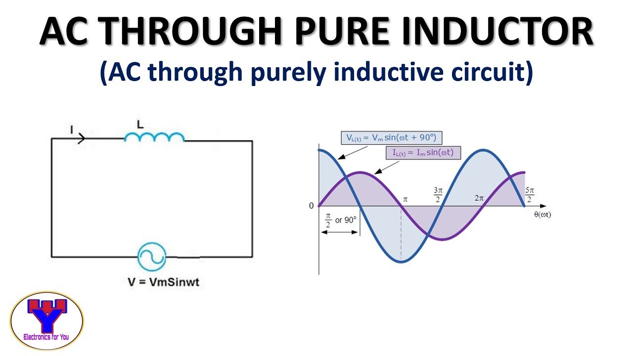
AC through pure Inductor | AC through purely inductive circuit - YouTube

PHASOR DIAGRAM ( INDUCTIVE LOAD) FOR A SINGLE PHASE TRANSFORMER - YouTube